|
|
Actuation Test
Equipment Co. |
|


A brief history of the Index Test Box
project
|
|
|
|
|
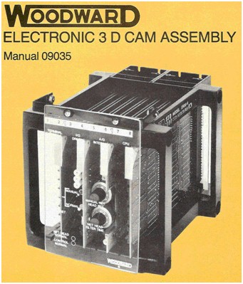
1975 - Woodward Governor Company introduced a new digital electronic 3-D cam for Kaplan turbine runner blades, replacing the hydromechanical 2-D Cams deployed at that time. USACE supplanted them with their own 3-D Cam controller because Woodward 3-D Cam had a potentiometer feedback on the blade-angle cam. USACE had a policy of never using potentiometers as feedback elements for critical control inputs. Woodward scoffed at this and didn't offer the logical solution of switching to a non-contacting resolver, RVDT or Rotary Optical Encoder with a significant upcharge. Instead, Woodward's position was, "We're the experts so do it our way. " USACE embarked on a DIY project that has arguably led to the Fish Mortality problem, Lawsuit and ongoing spill of ~$350M annualy. |
|
|
1985-To increase sales of 3-D Cams,
integral index-testing was offered to tune-up the unit by optimizing
its 3-D Cam profile. The first Index Test Box (ITB) Prototype was
initially field tested at Clarence Cannon dam on Mark Twain Lake in Missouri,
USA. This test validated the ITB and the Constant Power Method of
testing by a direct comparison of test results from the new Index Test
Box and the industry standard classical method of index testing.
According to a DOE Hydropower Engineer the Results were
positive, leading to productionization of the ITB and an offering for
public sale. |
|
|
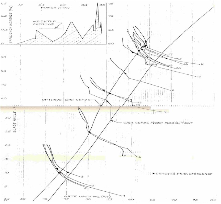
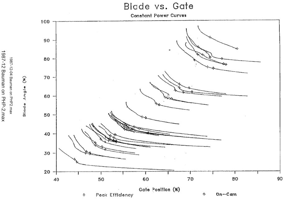
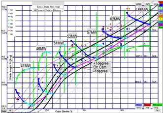
The Constant
Power method was used for this test. This test is run "on the
governor," with the unit operating normally - as far as the dispatcher
and control room can tell. The ITB sends a blade-offset value to
the 3-D cam, which pushes the blade above or below the on-cam position while
allowing the governor to hold power constant using the gates.
This sweeps the gates and blades together along the parabolic-shaped
"Constant Power" curves shown at left. Corresponding efficiency
curves on a second page locate the peak efficiency blade to gate point. |
|
The prototype ITB Field test at Clarence
Cannon Dam was scheduled to run concurrently with the USACE acceptance test on
the two turbines in this newly commissioned Dam and powerplant. Based on the
closeness of the ITB and conventional test results, BPA purchased an ITB
6-months later. |
|
|
|
1986 Bonneville
Power Administration (BPA) in Portland Oregon purchased the first production
ITB in 1987 for a "proof of concept" test for potential
use in the Federal Columbia River Power System (FCRPS) power plant. This test
was conducted by DoE at Portland General Electric Bull Run Power House
#2 (PGE-PHP-2). Successful test results were reported by engineers from PGE,
DoE and
Woodward. |
|
|
The Constant
Power method was used for this second field test in a DoE "Proof of
Concept" test at Bull Run. Success was such that DoE offered to purchase
113 ITBs from Woodward Governor, which would have included new governors and
3-D cams. Total cost of complete FCRPS turbine control system upgrades and
ITB installations was estimated >$25-million. USACE HDC declined
this offer, preferring to design and build their own automated index
testing device. |
|
|
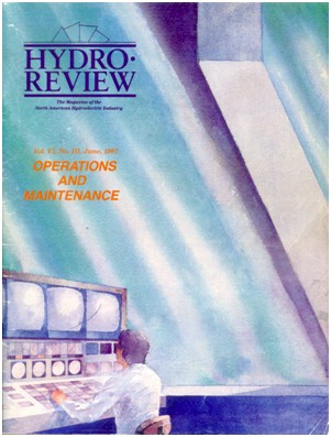
1987-Woodward's
Index Test Box was introduced in Hydro Review
magazine concurrent with the PGE-PHP-2 test.
This article reports on the 1985 prototype field-test at
Clarence Cannon Dam, describes index testing conventional methods and the new
Constant Power method, and explains the new Index Test Box methods and
techniques. |
|
|
Woodward's hydro
division was moved to new facilities in Stevens Point Wisconsin, USA and the
ITB project was transferred to other Woodward personnel. The next field-test
was unsuccessful and the hydro division faltered, failed and was sold to
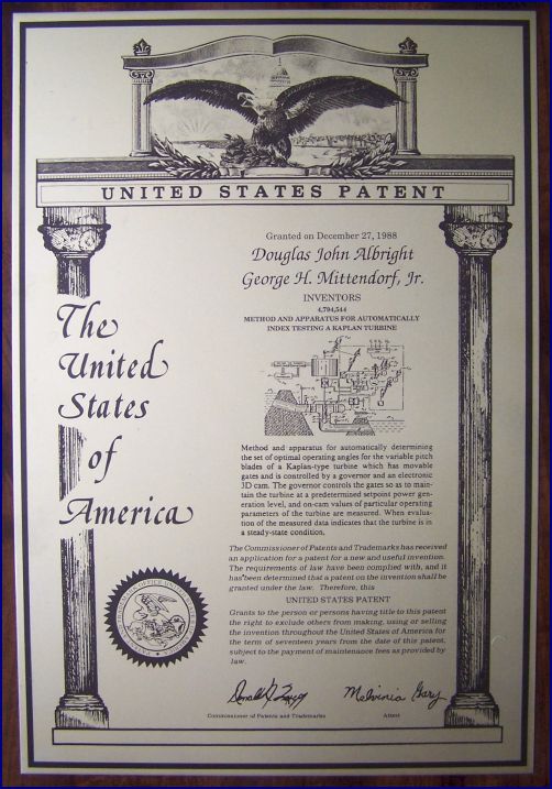
General Electric. The ITB patent went along with this sale, but the
technology it protected was never utilized. The patent expired in 2003
and the ITB technology came into the public sector. Actuation Test Equipment
Company was established to develop and market this new technology in
1993, but before any offerings were made, USACE Hydro Design Center (HDC)
contacted ATECo to inquire if an updated ITB could be purchased from the
inventor(s) listed on the ITB patent. |
|
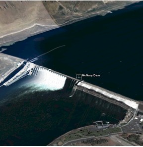
2005 -The
original Index Test Box design was updated to ITBRev-1. Two
sole-source solicitations led to USACE
purchasing one ITB on a sole-sourced contract for a second
"proof of concept" test at McNary Dam on the Columbia River in
Umatilla, Oregon. Testing at McNary in December 2005 was ultimately
successful, as described in ATECo's test report, HDC's Memorandum
for the Record and HDC's reports to DOE BPA Hydro
Optimization Team (HOT) meetings. All of the Government documents were
acquired via FOIA requests. |
|
|
|
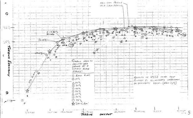
The Constant
Power method was used for this USACE "Proof of Concept"
Test at McNary. Test was mostly successful, but low flows were
unmeasurable due to extremely noisy Winter-Kennedy signal. A
rolling-average filtering algorithm was designed for the ITB signal
conditioner that allowed robust signal response while blocking high-frequency
noise. |
|
|
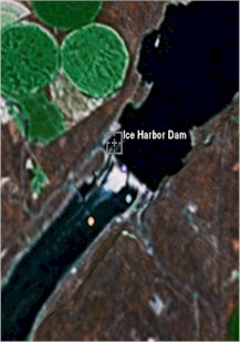
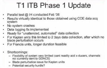
2006-A second field test at Ice Harbor
Dam was conducted to verify the fixes and that USACE personnel could operate
the ITB unassisted. The test was a parallel data collection
where USACE's normal data acquisition system was used for the
index-test while the Index Test Box was connected in parallel to
continuously record SCADA system data streams. The ITB data was downloaded and
sent to ATECo for analysis. The test results were sent to USACE HDC for
comparison with the official COE data reduction. The comparison and all COE
results were withheld from ATECo with no comment as to why. |
|
|
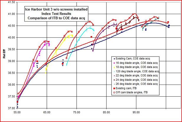
The comparison
was obtained years later via FOIA. It shows good correlation between the
reltaive test results from both the ITB and the COE instrumentation.
Subsequent FOIA documents from BPA HOT show duplicity by government personnel
who attempted to commandeer the ITB technology. |
|
|
The second
field-test was reported with a PowerPoint presentation by USACE
personnel to the HOT on 3 March 2006. This document was acquired from BPA by
FOIA request. The conclusion on the ITB field testing was that ITB test results
were; this test was even more successful. FOIA requests to HDC and
BPA were necessary to learn that HDC had reported to
BPA HOT that the "Results virtually identical to those obtained
using COE data acq system," and that ATECo's ITB was "Ready for
‘unattended, automated’ data collection." |
|
|
2008-A
second magazine article to introduce the new Index Test Box currently
being offered, highlighting the new Constant Power method and
statistical analysis techniques to determine SteadyState conditions. New
features include updated computers & software, relying on "lessons-learned"
from the experience with the Columbia river field
tests as a guide. The instrument configuration is intended for use at index
testing and long-term monitoring of turbine performance. |

|
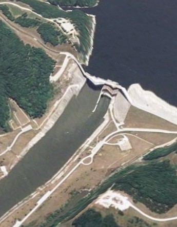
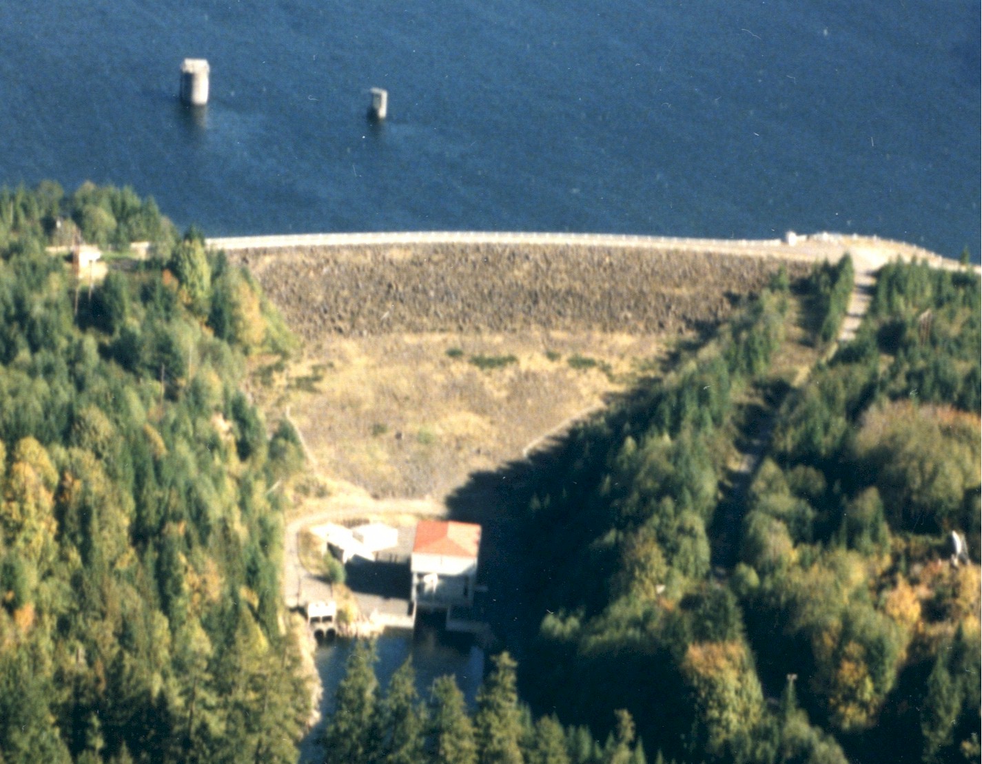
2008-North
American Hydro engaged with ATECo to initiate a project to optimize the
three Kaplan bulb-units on the St. Mary’s River in Sault Ste Marie,
Ontario Canada. This Google Earth aerial view shows the layout of the
approach and discharge canal of the power plant setting. Flow and wave
dynamics in the approach canal on the left-side present a difficult problem
for controlling these turbines and for capturing SteadyState index-test data
for efficiency performance evaluation of these turbines.
The index-test
procedure is to always approach every test point in the increasing gate
direction, which means the forebay sloshing is always at its perigee when
data points are captured. This error culminates in a 3-D Cam profile
shifted to a lower than documented head that has a detrimental effect on
overall turbine operating efficiency. This problem can
be completely avoided by using the Index Test Box Constant Power Method that
synchronizes the motions of gates and blades to sweep across the “On-Cam”
line to capture the efficiency data points for the existing power level
without affecting flow (or power) appreciably. The ITB testing
method is a continuous process that runs in the background rather than a
scheduled testing event. The SCADA system and powerplant data logger are
programmed and setup to record Forebay, Tailwater, Gate Stroke, Blade Angle,
Relative Flow and Generated Power continuously during normal operation of the
unit. , and data collection
method records data 24/7 collects and analysis the data in hours-long blocks,
gleaning SteadyState data points from Excellent
instrumentation and data logging equipment that were already present in the
power plant facilitated a new index-testing
method. Data collection uses the existing power plant
instrumentation during normal operation. A few modifications to the
instrumentation and turbine control system made index testing during normal
operation easy and economical. |
|
PT Interface
Synchronizer WGC MOD II Retrofit at Mica Design Manual |

