PT/VT Interface:
When Woodward's hydro division was dismantled, several of the engineers who had used this product in their governor designs at Woodward moved on to other hydroelectric control companies, yet still wanted access to a product with these same capabilities; but improved using new packaging options and electrical components that have become available in recent years. Contract manufacturing of these customer-specified modules is how ATECo got started building the ATE-30 in 2001. To date, over 300 of these modules have been supplied in various configurations and packages, without any significant problems or product recalls over the life of the product. One customer duplicated and redesignated the ATE-3X PT Interface as their own "VT Interface" and acquired a UL certification for it. A subsequent decision was made to manufacture these modules in-house, which released Actuation Test Equipment from the prior "captive-supplier" relationship, hence the ATE-31 VT/PT Interface was made available to the market as a product of Actuation Test Equipment Company. Inquiries from hydroelectric powerplants for spares of these modules has resulted in direct market sales at reduced prices to these end users. |
![]() The ATE-30 is in a Weidmuller enclosure |
![]() ATE-31 is in a Phoenix Contact enclosure |
The
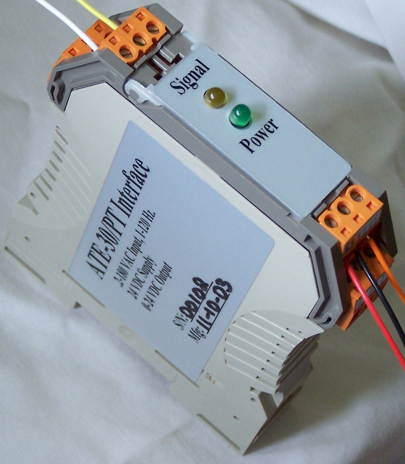
packaging configuration for the
ATE-30 and ATE-31 Potential Transformer Interface (PTInterface) modules
is
shown in the two pictures above. The circuit board layout and
design are
essentially the same; the electronic circuitry and electrical
performance of
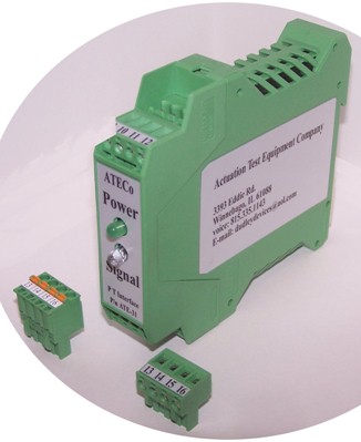
these two modules are identical. The original ATE-31
was designed
into the Weidmuller DIN rail mount (23 mm wide)
packaging. This
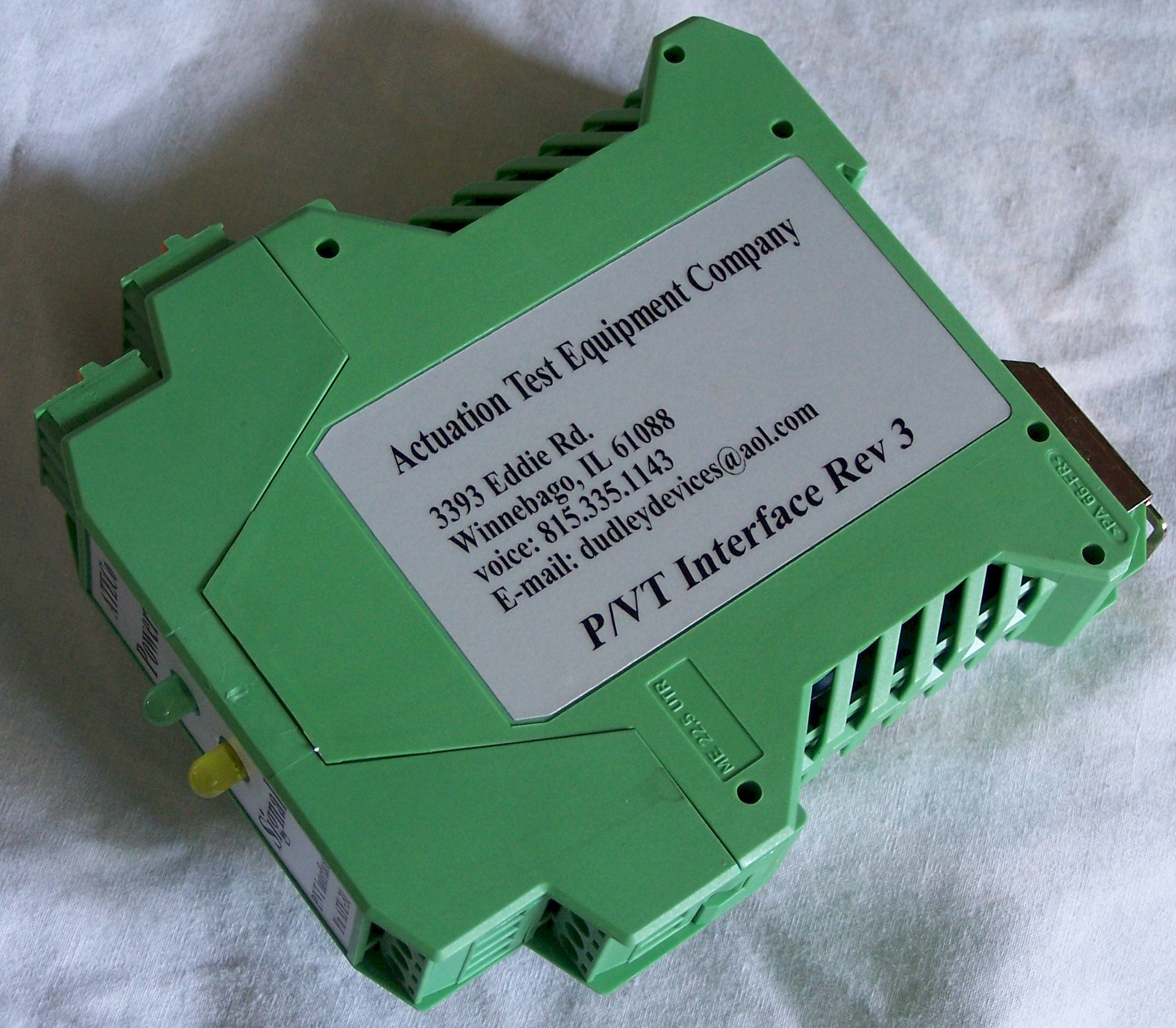
enclosure did not meet the CIE flame retardancy standards, so the
design was
improved by switching to the Phoenix Contact (23 mm
wide) DIN rail
mount enclosure. Both
of these signal
conditioners utilize the Analog Device AD210 isolation amplifier as the
primary
element, providing up to 3500 VDC isolation between the input
and the
output. For
this design and CIE
certification, the isolation was tested to 2000 VDC
isolation. Both
designs have the same electronic circuit in them. The
input accepts a voltage from an
instrumentation potential transformer and converts it to a 24 Volt
pulse train
for use by PLC-based frequency counting equipment. The input
amplitude
can vary from 0.2 VRMS to 180 VRMS. The input frequency can
vary from 6
Hz to 120 Hz. A 180
Hz 3-pole Butterworth
low-pass filter in the ATE-3X PTInterface prevents high frequency
noise, such
as that induced by operation of nearby switchgear from getting
to the
tachometer input. This filter blocks high frequency
transients
that may be superimposed upon the input signal
voltage from passing
through to the frequency counting equipment. The
amplifier sensitivity of the
Model ATE-31 allows it, in conjunction with a frequency
counter, to
reliably measure the frequency output of a generator operating at low
speed
prior to the application of field excitation. Typical
generator output at 10%
speed is greater than 0.2VAC. The
ATE-31 takes advantage of the
residual magnetism in the rotor and armature of the generator when the
unit is
"off-line." When
generator excitation is turned
off and the unit is governed in an isolated, "speed-control"
mode. Accurate
and instantaneous information
about turbine rotor angular speed is essential for robust dynamic
control
system performance. This
residual alternating
voltage is in exact synchronization with speed, and is ideal for a
tachometer
or speed controller. The
AD-210 amplifier circuit produces a 24 v
pulse train from a sinusoidal input; intended
to measure the
generator's residual voltage output while spinning at less than 100%
speed,
with generator excitation off. When
the excitation is on, the 110
VAC output of the PT circuit is sensed using a 15k Ohm 5W resistor and
a pair
of high-speed switching diodes.
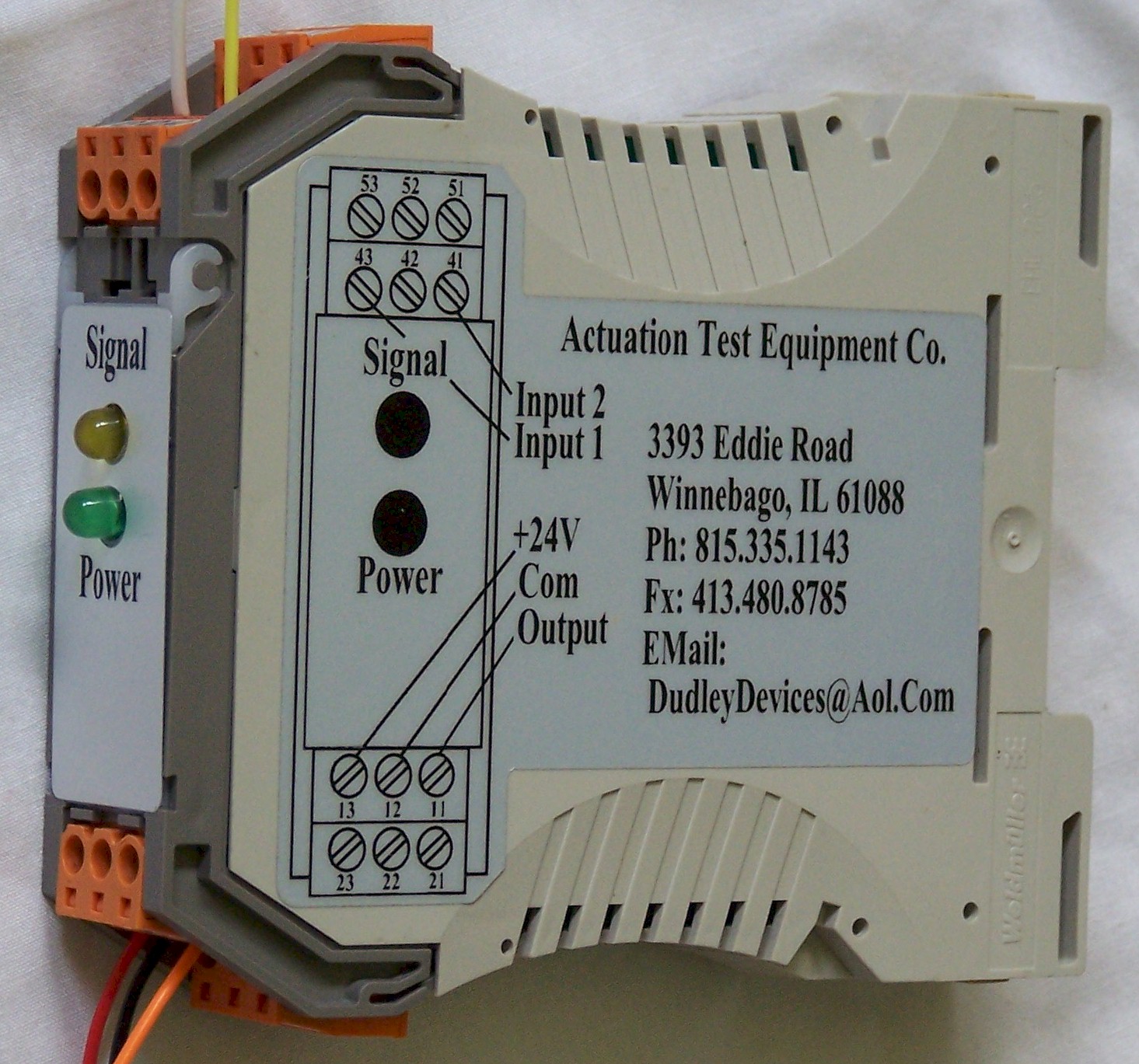
 The input stage of the Model ATE-31 is fully isolated from the output stage, so the signal input can be connected either from line to neutral or from line to line of the instrumentation potential transformers. The connector plugs are available in two styles, a screw-terminal and a spring-cage type. Two schools of thoght exist on which is the superior method, the simple solution for ATECo is to offer both, and let each customer decide which to use. The PT Interface |
![]() | The
Model ATE-31 PT Interface has two connector styles. The upper is a
spring-cage connector that is used by pressing on the orange clip lever
and inserting the wire into the opening. The advantage with these is
that the wire is always held tightly, and cannot work lose because the
spring hold tension on them. A traditional screw-terminal is also available. |
The ATE-31enclosure is available with an integral grounding wire to connect directly to system ground through the rear of the case.. |
APPLICATION The
Model ATE-31 PT Interface module is useful in
applications where the rotating speed of a generator must be accurately
measured without the addition of a conventional slotted disk or gear
and
magnetic pickups. It is
designed with sufficient sensitivity to operate from the voltage
produced at
low speeds from the residual magnetism in the rotor of the generator. Typically,
the residual output of most generators is
sufficient for the Model ATE-31 to allow measurement of the generator
speed
down to and below 10% of the rated speed of the generator, specifically
designed for use as an input to the unit braking system. The ATE-32 is not a creep detector. |
STATUS
LEDS The
Model ATE-3X utilizes two status LEDs. The
green LED indicates that DC power is applied. The
yellow LED is illuminated when the input signal
has positive polarity from terminal 11 to terminal 12. The
yellow LED is extinguished when the input signal
is zero or has negative polarity. At
low input frequencies, the yellow LED will flash
visibly to indicate the presence of the input signal. At higher input frequencies,
the yellow LED will
appear to be illuminated at a reduced intensity due to visual averaging
of the
flashes. |
CALIBRATION No
calibration is required for the Model ATE-31. |
SPECIFICATIONS
Power
Supply:
18 to 30 VDC
Consumption:
2 W typical Input
Amplitude
Range:
0.2
Vrms to 180
Vrms
Frequency Range:
6 Hz to 120 Hz Output
Pulse train 24 Volts peak-to-peak (typical) Mounting
TS32 or TS35 DIN Rail ATE-30 Pin
Connections:
21,
22, 23 & 51, 52, 53 Ground Bus 43 (+) Input 41 (-) Input 12 CT
Ground 11 Signal
Output 13 DC
Power (+) 42 No Connection ATE-31 Pin
Connections:
1,
2, 3, 4 & 13, 14, 15 & 16 Ground Bus 5
& 6 (+) Input 7
& 8 (-) Input 9 CT
Ground 10 Signal
Output 11 DC
Power (+) 12 No Connection
Operating:
0
to 55 oC (5 to 131 oF)
Storage:
-25 to 70 oC (-13 to 158 oF) |