 |  |
(33) Post | LinkedIn - V2500 Engine Preservation Demo.
INTRODUCTION
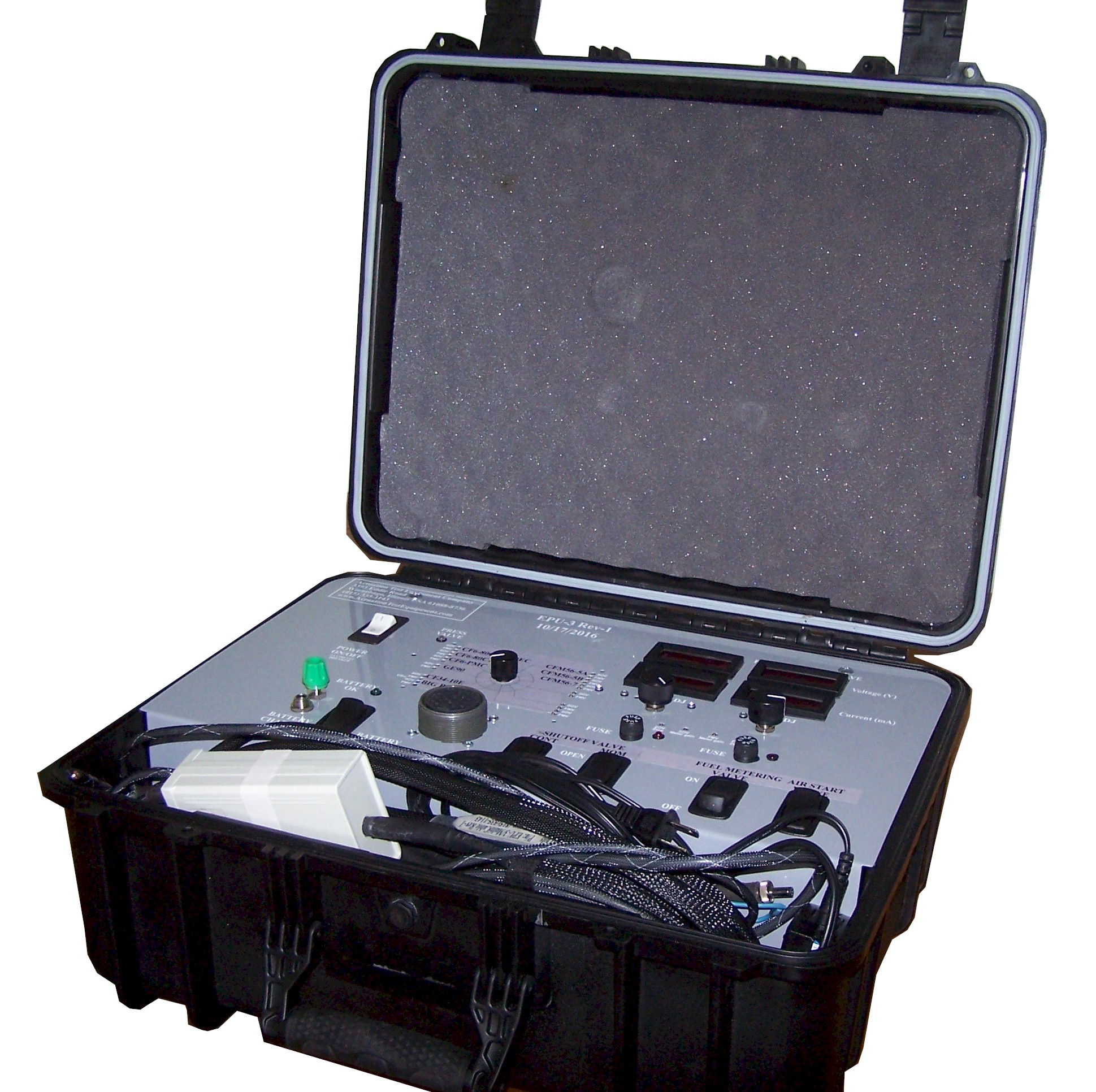
The Engine Preservation Unit is a battery powered service kit for opening the airframe fuel Shut Off Valve (SOV) and Fuel Metering Valve (FMV) on an "off-wing" gas turbine engine while monitoring the fuel Pressurizing Valve Indicator (PVI) switch.
An "Air Start" switch has been provided to provide 24 VDC (limited by 2 Amp fuse and a 5 Ohm resistor placed in series) for remote operation of the Air Start Relay.
Connector Catalogs
Pyle MIL-DTL-83723 Circular Connectors
Wire suppliers WireMastersSEA WIRE AND CABLE
This is a good search tool of multiple vendors for parts
Electronic Component Search of Authorized Distributors | TrustedParts.com
An
assortment of engine-specific cables have been designed and used for a wide
variety of engines at a low initial investment.
To define a new cable set, the Connector partnumber, pinout and SOV and FMV signal levels to use.
The current list is:
- CF6-80C2 FADEC 2
- GE90-115
- CF34-8C
- V2500
- LEAP engines
The SOV switch is a momentary contact to open and close the fuel Shut Off Valve (SOV).
The FMV switch is a continuous contacting on/off type to open the Fuel Metering Valve (FMV).
Cat-O-9-Tails
A novel cable configuration has an array of aircraft connectors splayed out from the EPU-3 Connector.
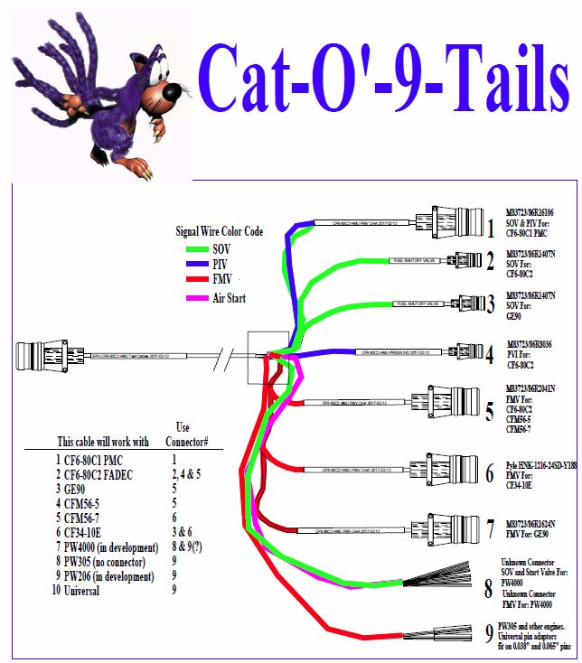
This cable set is a combination of an end-user selected mix of cables to make a single cable set.
The basic cable set includes the wire, protective sheaths, labling supplies and the breakout box, all -pre-assembled and ready to install the connectors.
The EPU has 5 basic functions:
- Battery Test
- Air Start Solenoid
- Shut Off Valve Current
- Pressurizing Valve Indicator
- Fuel Metering Valve Current and Polarity
New functions that have been considered
- RPM on core engine rotor for pump-RPM threshold to open FMV for automatic control
- RPM for CF6-80C2 N1 Sensor
- Variable Stator Vane control
- Variable Bleed Valve control
The EPU-3 has 4 electrical outputs to the engine:
Air Start Solenoid is fused and current limited by a 5 Ohm series resistorPressurizing Valve Position indicator supply current limited to 20mA
Shut Off Valve current limited at 500mA.
Fuel Metering Valve current up to 200mA.
Additional features include:
Battery charger input
Battery check switch
Schauer Battery Charger - JAC0224 manual.pdf
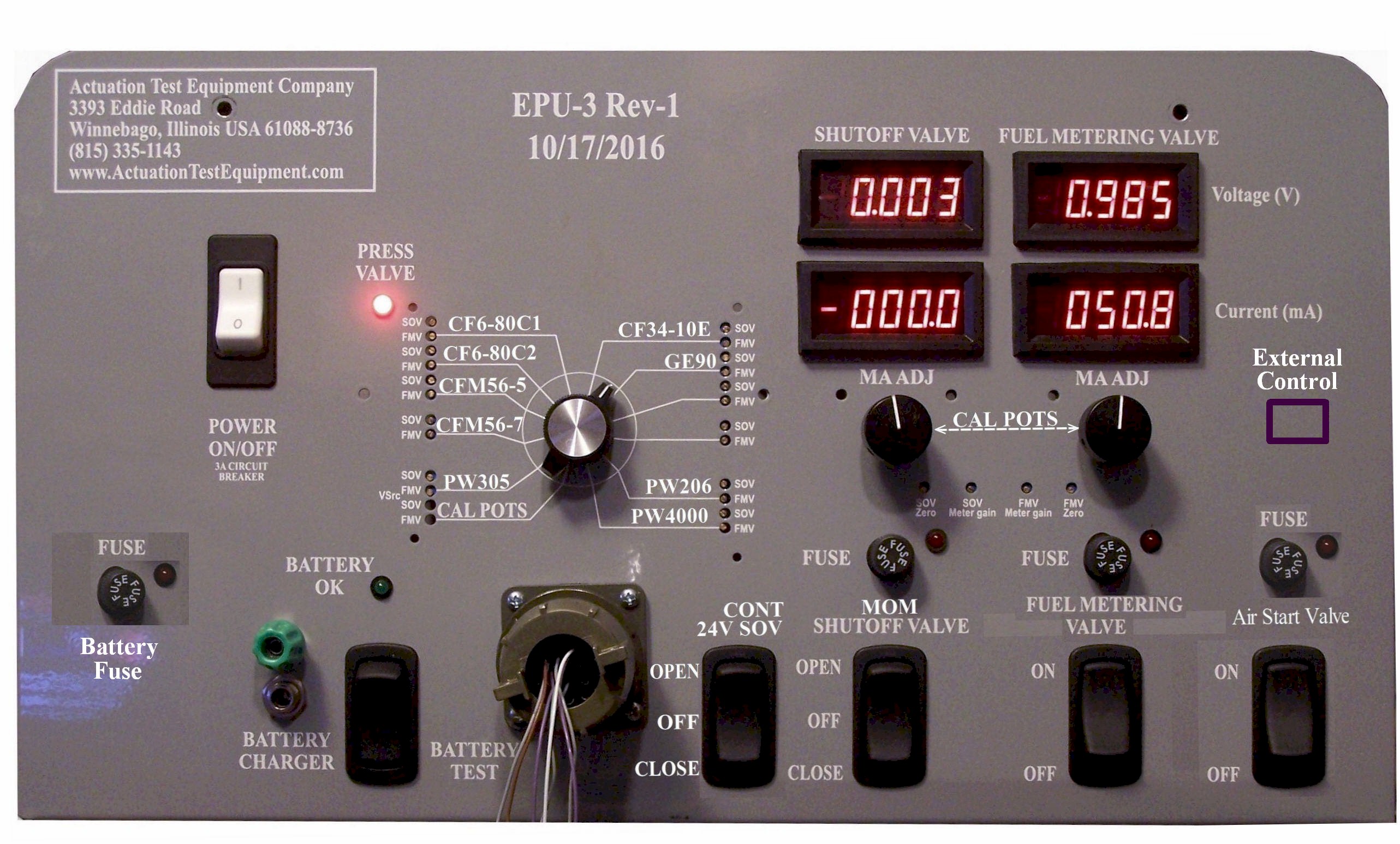
CONTROLS AND INDICATORS
The POWER ON/OFF switch is also a 3A circuit breaker.
The PRESS VALVE LED shows the position of the Pressuring Valve Indicator (PVI) switch.
The Rotary Selector Switch connects a pair of preset potentiometers for SOV and FMV current SetPoints at each switch position to the input of the current regulators.
The CAL POTS position on the Rotary Switch connects the two large MA ADJ potentiometers on the right side as the SetPoints to the current regulator circuits.
An external 24VDC BATTERY CHARGER is connected using a screw-coupled connector.
When pressed, the BATTERY TEST switch compares the battery voltage against an internal 20V Zener diode. If battery voltage is higher than 20 volts the BATTERY OK LED illuminates.
The dual-position, momentary contact SOV rocker switch energizes either the Open or Close coils of the fuel valve.
The FMV switch ergizes the coil in the fuel metering valve.
LAYOUT OF CONTROLS
The current regulator circuits are arranged in two columns for SHUTOFF VALVE and FUEL METERING VALVE.
The SOV DPDT momentary (On)-Off-(0n) switch routes the output current to either the OPEN or CLOSE coil of the SOV solenoid. Current flows through a front-accessible fuse socket/holder capable of holding a wide variety of English and Metric sized slow-blo and fast-blo fuses.
The FMV switch turns the FMV current on and off. The SOV and FMV current regulator circuits are electronically identical, but configured with different current and voltage ranges.
Setup Procedure for the Rotary Switch
Getting the right connectors
The engine manufacturers
Determining the turquemotor pins
Set SOV switch tarting with
The two Voltage display digital panel meters have a 0-20V span. When over-voltage is present, the meter display blinks at about 1 Hz.
This is a handy continuity indicator for the SOV and FMV coil circuits.
The output voltage of the current regulators when no current can flow because there's not coil present gets up to over 22 volts, which is slightly over-range for these meters.
If the panel meter get more than 20V on the inputs all of their display segments will flash, indicating an over-range condition.
The over-range in this case is not great enough to be a problem, and actually serves as a handy indication that the coil circuit is incomplete and something needs to be plugged in.
The regulated SOV and FMV currents flow through fuses to the output connector.
The ultimate over-current safety is a fast-acting fuse of appropriate amperage.
Select the fuse amperage to be the next- higher value above the maximum the solenoid or torquemotor coils should ever see, and use fast-blow fuses for maximum protection.
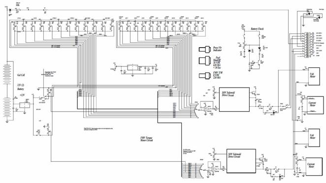
Block Diagram
This simplified block diagram will help to understand how the EPU works.
zizi
Figure 1 EPU-3 Block Diagram. (Click Image for .pdf file download.)
The FMV output max current level is 200mA and max SOV current is 500mA.
The LED next to the fuses illuminate when
voltage is applied with a blown fuse.
METERING
CIRCUITS
The Voltage (V) meters are differential voltage measurements taken directly across the SOV and FMV coils.
These Datel® DMS-40PC-1-RS panel meters have +/- 1.9999 displays to indicate measured voltage range of +/- 1.9999* volts.
A voltage divider with calibration pot allows using the same meter for both SOV and FMV.
When the input voltage exceeds this maximum*, the display blinks all of its segments on and off indicating an over-range. This wee bit of overvoltage won’t hurt anything. In our case it just means the cables are disconnected.
The Current (mA) meter measures return current as the differential voltage drop across a 1 Ohm resistor in the return path.
Safety Features
Output current is held to the SetPoint
current levels regardless of output impedance by a high-side sense current
regulator circuit. Failure mode analysis showed that if torquemotor drive
current is sensed on the low side (like the majority of test stand PMC
simulators are set up), if the return-path conductor wire is shorted to ground,
the current regulator loses its feedback signal and output current goes to its
maximum value. Using high side regulator avoids this potential over-current
situation.
The EPU-3 has current limiting resistors in
series with the output current to prevent potential harm by simply limiting the
maximum possible current with a 50 Ohm coil load to 350 mA, the maximum current
rating for a large torquemotor.
Testing Battery Voltage
To test the battery voltage before heading out to perform a preservation procedure, press the Battery Test Switch up, and observe the green Battery OK LED illuminates.
Setting Up the Rotary Switch
Set the Rotary Seitch to its Big Pots position
Set the engine up for the preservation by replacing the fuel inlet hose to the main fuel pump with a hose with preservation oil pressurized at 50 psig or so...
Start the huffer, open the Shut Off Valve with the EPU-3, open the air start valve either electrically or mechanically to get the engine spinning, when the pressurizing valve opens rotage the FMV Big Pot clockwise slowly, observing the currentmeter to make sure you dn't over curren the engine's fuel metering valve torquemotor.
Typical range is +100mA. Null Currents are typically between 20 and 40 mA.
Fuel metering valves are integrators, in that if the FMV current null is 20mA, and the current is 21 mA, the Fuel Metering Vavle will move slowlly in the opening direction until it is fully open.
If the current is 19mA, then the FMV will move slowly in the
Connect the calibration tool
Set the rotary switch to the desired position.