HYBRID INDEX TEST METHOD FOR
KAPLAN TURBINES
ACTUATION TEST EQUIPMENT COMPANY, INC
Winnebago, Illinois
August 27, 2017
Diagnostic Features
Kaplan gates and blades must be positioned accurately and robustly in order to maximize the turbine's generating efficiency and service life.
The first phase of any index test is a thorough checkout of the unit’s control system.
The Index Test Box (ITB) was developed at Woodward Governor Company in 1984 as a dual-purpose test instrument; the primary function is Kaplan turbine optimization to tune-up the 3-D cam surface profile. Secondary, but equal in import is the diagnostic analysis of the turbine control system behavior.
A third function for Condition Monitoring has recently been added to enhance the ITB’s utility value.
The ITB provided remote diagnositc analysis and index-testing capabilities using off-the-shelf IBM Pc type computers and data streamed from the existing powerplant SCADA system over normal office LAN or Ethernet communication.
This allows the engineers back in the office to
observe and diagnose turbine control systems behavior in the field, in real-time over
the Internet.
Setup and Instrumentation
Modern powerplant SCADA systems typically have the necessary instrumentation for an index test, except in some cases the Winter Kenney taps are non-existent or blocked with sediment. Every unit in every powerplant will be different.
To setup a unit for these tests the
governor is modified to provide signals to the SCADA system for gate setpoint,
blade setpoint, blade position and governor inputs are added for manual gate
and blade positioning. Many turbine governors don’t bring out these signals to
the SCADA system. In every case, the usual powerplant’s engineers and
technicians have been able to do this setup work. Next the SCADA system is
configured to bundle the required signals and route them to the existing powerplant
data logger.
1.
Forebay
2.
Tailwater
3.
Gate Setpoint
4.
Gate stroke
5.
Blade Setpoint
6.
Blade angle
7.
Flow (Winter Kennedy or
other flowmeter signal)
8.
Power (Watt transducer
output).
9.
Grid frequency
10.
Grid voltage
The powerplant data logger is reprogrammed to scan the above listed signal channels, add a scan-count and date/time stamp and record scans twice/second. Data is recorded continuously while the machine is operated normally.
Whenever an interesting event occurs, data files are sent by sneakernet to ATECo for analysis.
The first concern is to determine if the govenor is robust, accurate and precise enough for index-testing "on the governor."
The ITB software is not needed for most of these
checks - simply looking at the data in an Excel spreadsheet and knowing what to look for will show up many
of these problems.
Kaplan Off-Cam Index Testing Procedures
There are 3 ways to test a Kaplan turbine off-cam.
The most common is Fixed Blade, swept gates and power.
The second is Fixed Gate, swept blades and power.
The third is the Constant Power, moving gates and blades
The Fixed Blade method is the most commonly used because on most existing governor cabinets the gates are easier to control using the Gate Limit than the blades are to control by climbing up inside the governor cabinet to make adjustmenst to the thumbscrews on the blade hydraulic-amplifier's floating lever.
method is vastly superior for testing a single run of the river turbine with
small forebay and tailwater.
ITB Prototype Test Demonstration (1985-1986)
Woodward’s first ITB was
field tested in conjunction with the acceptance test of a 33MW vertical Kaplan at
USACE’s Clarence Cannon Dam. USACE test engineer Don Sachs was a proponent of
the Constant Power index testing
method that the ITB embodies, but HDC insisted that the classical Fixed-blade test method be used for his index test. This
author was recruited into his index-testing crew as the “governor man.” A12-man
USACE test crew performed the index test according to the procedures laid out in HDC’s
“Red-Book.”
Because Lee’s
tutorial on off-cam Kaplan index testing was the recipe used to design the
original ITB, both sets of test data were forwarded to Lee at BPA for
evaluation. Lee prepared a
comparative analysis report of these two data sets, prompting BPA to purchase
the first ITB from Woodward 6-months later.
Demonstration of Woodward’s ITB at Bull Run Dam (1987 to 1988)
When the original ITB was developed at Woodward Governor Company a U.S. Patent was acquired to protect the new instrument. The first test was at Portland General Electric’s (PGE) Bull Run Dam (PGE-PHP-2) located about 30-miles East of Portland, Oregon. The field-test at Bull Run went exactly to plan, according to field-test reports by Lee Sheldon, Gary Hackett (senior staff engineer from PGE) and Terry Bauman (The engineer that Woodward hired to take over the ITB project after I returned to Woodward’s aircraft development lab).
Because he didn't have a dog in the fight - Gary’s conclusion was the
most compelling of the three:

An
article in Hydro Review pitched
the new ITB from Woodward.
After this successful test BPA offered to procure
ITBs for all of USACE’s large Kaplan turbines in a project estimated to exceed
$30-million to acquire the new governors, 3-D Cams and ITBs, but instead of
accepting this FREE proven equipment that BPA would purchase from a world-class
supplier (Woodward) using DOE's funds, HDC engineers attempted to duplicate Woodward’s ITB with
their own design at DOE expense. A
BPA report on this project was acquired years later; despite the report’s encouraging
words the project had failed to achieve its objective and was quietly abandoned.
Woodward shelved and abandoned the ITB project after the government didn’t buy
them.
This
author quit Woodward in 1992 to startup the
Actuation Test Equipment Company (ATECo) to resurrect the ITB as a new
enterprise. When a prototype was ready Woodward was approached to add a
proven automatic
self-optimizing capability to their Kaplan governor. Threats
of lawsuits kept the ITB out of the market. Woodward didn't want
it, but they didn't want anyone else to benefit from it either.
This and other blunders by Woodward’s
hydro managers led the division to becoming so unprofitable that
corporate
managers sold the entire division to GE for $1 to sweeten the deal
when negotiations were underway to sell Woodward’s Engines and Turbines
division to GE. GE got the Patent with the hydro division, and
when they were approached with the ITB
a month later they were also not interested. So the ITB sat idle until
the patent expired 17 years later.
Experience with ITB at USACE HDC
(2003 to 2008)
In
2003 Lee was working at HDC as a rehired annuitant tasked with index
testing
all 113 of USACE’s large Kaplan turbines on the Columbia River under
the asupices of the fish-mortality lawsuit in Federal court. The patent
had
expired 2-years early because GE neglected to pay the 3rd renewal
fee. Rod Wittinger said he had been watching the Patent and when he saw it had expired,
directed Lee to contact this author to acquire the detritus of Woodward’s ITB
project as the start of a government project to resurrect the ITB - but ATECo
had already beaten them to it. HDC purchased a 2nd generation ITB
from ATECo on a government
contract after 2 sole-sourced solicitations (#1 #2).
A U.S.
Copyright was acquired to protect the software source code intellectual property. This version of
the ITB consisted of an IBM PC with a National Instruments I/O board and
Software Toolbox TopServer OPC communication program. The ITB was connected
directly to the GDACS SCADA system via a Cat-5 LAN cable and TopServer OPC program.
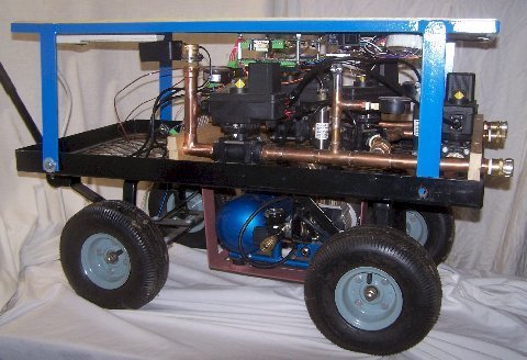
Figure 1 ATECo Pressure Transducer Cart with Electric
Flushing and Integral Air Compressor
A
pressure transducer cart was constructed by ATECo to facilitate moving the
ITB from machine-to-machine in a powerhouse. The ITB was deployed to McNary and
Ice Harbor Dams. At McNary, 2 ATECo personnel attended the test conducted by
government personnel. At Ice Harbor, government personnel ran the ITB without
anyone from ATECo present. The desired configuration had the ITB residing in
the control room and the transducer cart moved from machine to machine.
ITB Test at McNary Dam (December
2005)
Rod
Wittinger’s report on the test at McNary explains how the turbine was
manually exercised to the required gate and blade positions while the ITB
monitored the SCADA system’s data, and when Steady-state operation was detected
at each test point, the ITB automatically started recording data scans. Many
steady-state scans are collected at each test point and evaluated later by a
PostProcessor step to pick out the best test points. The ATECo
test report explains further.
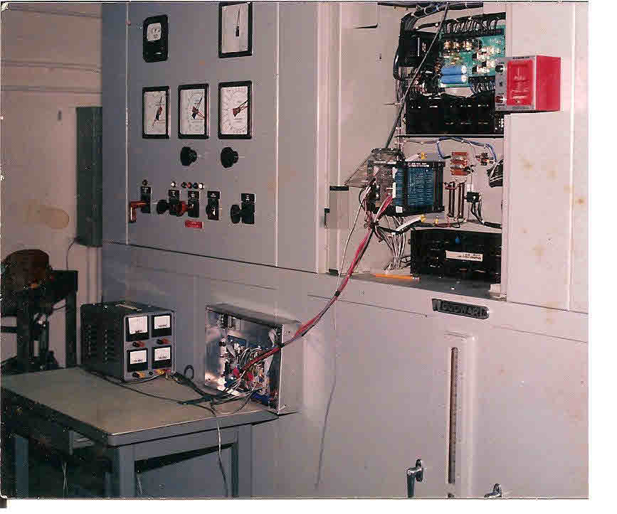
Figure 2 ITB Test Data from McNary Dam
ITB Test at Ice Harbor Dam
(February 2006)
For
this test the ITB was only used to monitor and record data in parallel with a
classical Fixed Blade manual index
test conducted by HDC’s test engineers using their customary methods and tools.
When the test was completed, the “canned” data from the ITB was emailed to
ATECo for analysis. When the reduced result was returned, HDC’s engineer
charted the comparison of both results in an Excel® spreadsheet.
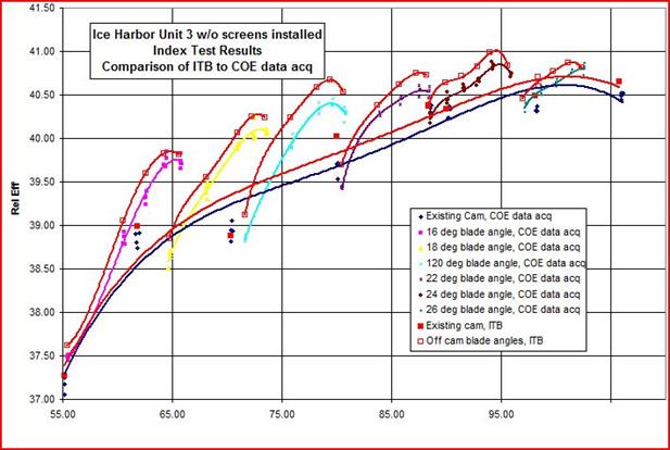
Figure 3 Index Test Results for COE and ATECo
Instrumentation
His
internal HDC memo reported on the test. The graph above has a slight offset
in the Winter Kennedy calibrations to show the similarity of the results. If
the calibrations had been equivalent, the efficiency curves would have laid right
on top of each other. In the subsequent test report to Bonneville Power
Administration (BPA) Hydro Optimization Team (HOT) USACE personnel said that
the ITB results were “Virtually
identical to those obtained using COE data acq system,” and that the ITB
was “Ready
for unattended automated data collection.”
Lee Sheldon* commented that the ITB data had less scatter than the
conventional data, falling closer if not right on top of the efficiency curves
for individual fixed-blade sweeps. After this successful test, instead of
buying the proven ITB from ATECo, government engineers initiated a project to
reverse-engineer the ITB in an internal government project. This all happened 10
years ago and by every indication (Periodic FOIA requests are keeping tabs on
them), they’ve been un successful just like when they attempted to duplicate Woodward’s
original ITB in 1990 with their “automatic
index testing device,” submitted to BPA as a potential surrogate to
Woodward’s ITB.
(*Please feel free to call Lee to
verify any of this, we’re currently working together on the project to index
test the 5MW turbine discussed herein: 503-356-8302)
Experience at Clergue Powerplant in
Sault Ste Marie (2009 to 2013)
The
best use of the ITB is when it can be connected to the SCADA system so that
sample rates of a KHz (more or less, depending on the computer and I/O board
selected) allow higher sample rates. A cavitation monitor and alarm in the ITB
would be a valuable feature, but due to powerplant politics and policies a
direct connection is forbidden. Most powerplants prohibit connecting strange, new
equipment (like the ITB) from unknown suppliers (such as ATECo) to their SCADA
system without first vetting the supplier and scanning for viruses and malware
- and in many cases there’s no money in the budget for it. This was the case at
Clergue in 2009. The ITB was demonstrated to work with North American Hydro’s
(NAH’s) new governors planned for the 3 turbines there. Dave Kornegay, NAH’s
project engineer had worked alongside me in 1984 when I developed the first ITB
at Woodward. Dave knew that the ITB would work for his governor designs at NAH
and wanted to add a “self-optimizing” feature to his Kaplan governor.
Unfortunately, Brookfield Renewable Power (BRP) had a policy of not allowing any
computing equipment or internet connections to their SCADA system and the money
for the new ITB hardware had not been approved. Dave really wanted this feature
on his governors, so along with Andrew Punkari (Andy) BRP’s project engineer,
Dave setup the governor software and prepared specifications for the governor,
powerplant instrumentation and SCADA system software changes; Andy programmed
the powerplant data logger to capture scans at a 2-Hz sample rate. All of this
was accomplished by the powerplant personnel using the pre-existing powerplant
equipment and sensors; most of the necessary signals were already in the SCADA
system so setting up the recorder was simple and straightforward. Data was
collected for several months and sent to ATECo periodically.
Another prohibition at
Clergue was because their contract with the power marketing agency stated that
if the machine was run in a test-mode (i.e. off-cam) the price paid for the
power was halved. BRP managers balked at the reduction in their revenue stream
so off-cam testing was disallowed. To get around this prohibition, a
blade-offset was added to the governor and HMI so that slightly off-cam data
could be acquired. Blade offsets were changed every few days, keeping within a
range of +3.0%. When the ITB test results were compared to the Hatch
Acres 2006 index test results good correlation was found. Unfortunately we were
unable to finish the testing because Andy was dispatched to
make repairs at another powerplant 200 miles distant and was gone for over a
year, so the ITB testing waited. Before he returned, Alstom bought NAH and Dave
jumped-ship to move to Innovative
Automation - who did not have a spot for the ITB in their product line.
Necessity is the Mother of Invention
By modifying the
existing governors, instrumentation, SCADA system and data logger to collect
the required data, and having the operators position the gates and blades
manually while the powerplant data logger stored 2 scan per second, the data
for a Kaplan off-cam index test can be collected in 4-hours. Low cost CDs,
thumb-drives and high-speed broadband Internet transfer of data files provide good
alternatives to a direct connection to the SCADA system. The most beneficial
result of this is the logistics of sending expert test personnel to the dam are
no longer necessary.
This
short video was prepared to publicize our method:
Figure 4 ITB SteadyState Analysis Display and Link to
Clergue Video
Click here:
Http://www.youtube.com/watch?v=C62uu2Cntx0
Current Field Test (December 2015
to present)
Lee
Sheldon got the job to index test a 5MW vertical Kaplan turbine and engaged
with ATECo to utilize the ITB’s Hybrid Index Testing capability for the job.
The facility is a flood control dam that was electrified after 63 years. An
index test was sought for the new 5MW vertical Kaplan to develop an optimized 3-D
Cam surface for this machine. An off-cam index test was needed to correct the
myriad issues that affect the optimum shape of a Kaplan turbine’s 3-D Cam head
and gate to blade surface.
Pre-Index Test Control System
Checkout
A
proper index test includes a dewatered inspection of the unit so that the
surface condition of water passageways and turbine working surfaces can be checked
and the full range of gate and blade motion can be verified from squeeze to
full open while the normal powerplant instrumentation and index testing
equipment are adjusted and calibrated. In lieu of such a comprehensive
inspection, with the above described modifications to the system software a
modest review of the data characteristics and time-response behavior can
determine if gate and blade movements conform to ASME and IEEE performance
standards. Below are a few examples of how this remote data observation
capability discovered problems with the Kaplan control system.
This
first check found a problem with the synchronizer. Getting a unit in sync with
the grid before closing the breakers on startup is a tedious and precise
requirement of the turbine control system. Most governor systems use an
external accessory such as Basler Electric’s
BE1-25A Automatic Synchronizer for this. This data from the 5MW Vertical Kaplan shows that
rotor bounces against the rotating magnetic field when the breaker is closed on
startup, which indicates the synchronization may not be adequate. This was seen
in typical operation data recorded during a normal startup.
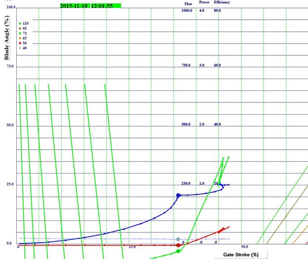
Figure 5 ITB Cartesian coordinate display during normal
startup
The
green lines on the left side are efficiency spikes that indicate the rotor was
not spinning at the same exact speed as the stator’s magnetic field when the
main breaker was closed. The unit should be at “speed-no-load” with flow but no
power generation i.e. a slightly negative efficiency value. What is happening
here is when the breakers close the rotor bounces against the rotating magnetic
field until it is pulled into synchronization. This may or may not damage the unit,
depending on how far out of sync the unit is when the breaker closes. In any
event, the control system should synchronize the unit to the grid better than
this for reliable long-term operation.
Another
problem was found in the stripchart traces from viewing the datalogger files
using Microsoft Excel®.
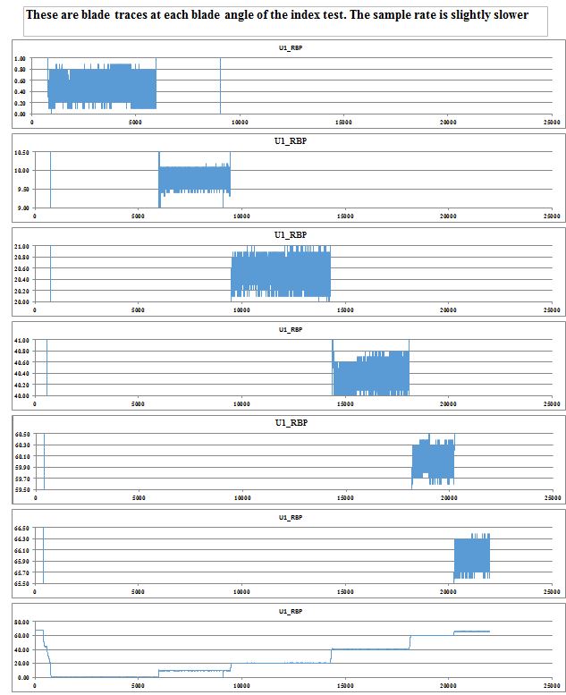
Figure 6 Excel® Stripchart Display Showing Blade Instability
At first glance the bottom trace in the chart above was
noticeably thicker than the others, so it was magnified at each blade value used
for the index test to investigate further. The Y Axis on these trace are blade angle
in percent and the X Axis is number of scans where each scan is 0.51 seconds
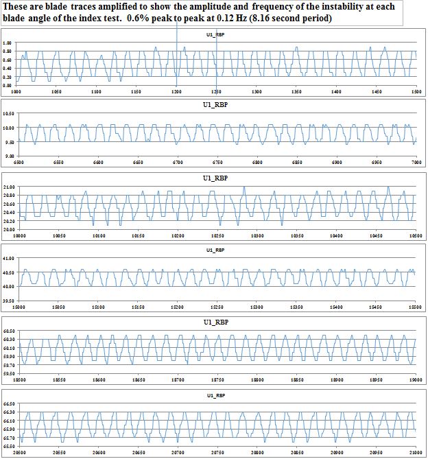
Figure 7 Excel® Stripchart Display of a Magnified View of the Blade Instability
This
blade trace display is magnified to show the amplitude and frequency of the
instability. The blades are always moving about 0.6% to 2.0% p-p with about an
8-second period. This is most likely caused by a positive lapped pilot valve on
the blade servo.
Another problem found
with the PLC-based Kaplan governor with a 3-D Cam and blade controller and an external
AGC in the SCADA system. This next graph shows the normal startup of this machine.
When generation is ramped up, the gate/blade indicator moved from left to right.
When it got to the 40-ft head line, the blades tracked up the 41ft blade cam
line instead of 46 ft, then the gates stop moving at 85% and the blades
continue going straight up, causing further increases of flow and power after
the gates stopped. At this point the AGC sees that power is too high and the
gates are closed a bit, and then the blades come back down a short time later.
This chart shows how the gates and blades continue to chase each other before
finally settling at the 41 ft on-cam line at the far right.
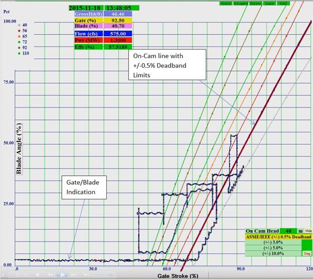
Figure 8 ITB Cartesian Coordinate Display showing 3-D Cam
Output Problem
This
chart shows conflicts between the governor, sluggish blade to gate relationship
and Automatic Generation Control (AGC). The two red lines immediately above and
below the heavy blue "On-Cam" line are the ASME prescribed 1.0%
deadband for proper blade positioning.
A
few more examples of problems detected at Clergue are included below:
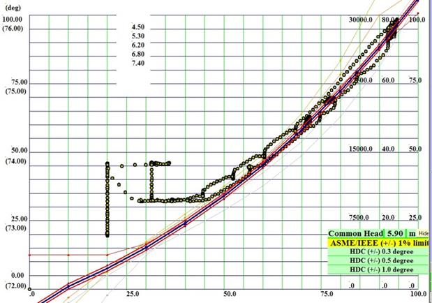
Figure 9 ITB Display of Gate/Blade
motion of Kaplan Bulb Unit with NAH Governor
The chart above shows
the actual gate/blade relationship when the new governors were installed. The
blades and gates mostly track the on-cam line at the high end, but something
screwy is happening at the low end. Below 30% gate the blades change direction
and go up to about 45% blade angle instead of tracking down along the on-cam
line. When this was showed to the governor engineer he consulted with the
programmer and this got fixed.
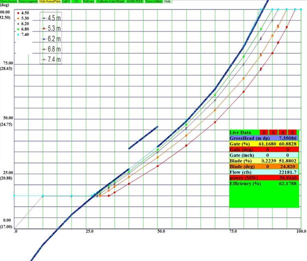
Figure 10 ITB Display of Gate/Blade
motion of Kaplan Bulb Unit with NAH Governor 3-D
Cam Data Table Bug
A second problem was
seen in the on-cam line when head was above 6.8m. The cause was an error in the
lookup table at the highest head. Again, as soon as the problem was seen, the
programmer slapped his forehead and fixed it in a jiffy. Without this Cartesian
coordinate display he wouldn’t have caught this problem until it was in the
field, and then he’d be fixing this under the customer’s nose.
Conclusion
These
real-world problems are not presented herein to be critical of anyone’s workmanship;
instead they are here just to show the utility value of observing the gate/blade
behavior of a Kaplan unit with an X-Y Cartesian coordinate display in the
field. If the problems can be observed and repaired during installation and
setup of the governor, everything will go smoother. In many cases, the decision
makers are business types or civil engineers; unfamiliar with governors and
their dynamic requirements.
Sincerely
yours,
Douglas
Albright
Actuation
Test Equipment Company
(815)
335-1143